In many fields, particularly space and aeronautics, transporting hydrogen in a liquid state is often the only solution. This requires very well insulated reservoirs. In this context, we have been asked to characterise materials in cryogenic conditions.
What kind of insulation is needed to store liquid hydrogen ?
To find out, you need to measure the performance of these different types of insulation :
- loose insulation
- Aerogels
- MLI (Multi Layer Insulator)
To assess this, we have developed a standardised platform for measuring vacuum insulation in cryogenic conditions. This device complies with the ASTM C1774 standard. This experimental device is also operational on loose insulation such as aerogels. The device also operates at atmospheric pressure if required.
This article describes this device, which will be upgraded in the coming months to measure up to 20K, the temperature at which liquid hydrogen is stored.
This device is part of a set of measurement benches that have been developed to characterise components and materials down to 20K (thermal conductivity, modulus of elasticity, dilatometry, etc.), because although measurements at 77K are currently being carried out, we would like to be able to go lower in temperature to meet the growing demand for characterisation.
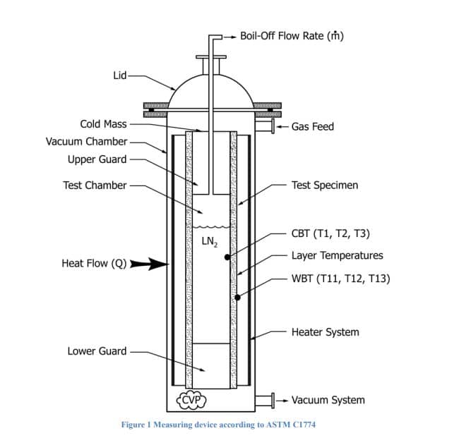
A measuring device has been developed to measure the thermal resistance of a super-insulator (e.g. a multi-layer insulator). It consists of a cylindrical tank with an external diameter of 114 mm and a height of 450 mm. This measuring tank is flanked by two other cylindrical tanks of the same diameter and 100mm high. The device is similar to the one described in ASTM C1774 in Figure 1. The three tanks are filled with liquid nitrogen. The two tanks at the ends act as thermal guards. The power passing through the insulation is measured by the mass flow rate of vaporised nitrogen, knowing the latent heat of the nitrogen.

Measuring devices :
The temperature of the inner chamber is 77K. The outer chamber is measured by several
thermocouples glued to the outer chamber.
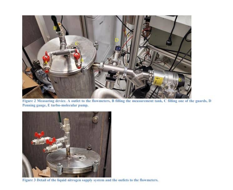
Flow rates are measured by two mass flowmeters specially calibrated for pure nitrogen. The two flowmeters cover the entire useful flow range.
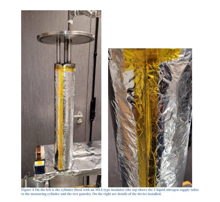
The system is shown in Figures 2 to 5.


Principle of measurement :
ASTM C1774 suggests calculating the power delivered through the insulation using the
following equation:

Where Q is the power in W, 𝑉̇ is the volumetric flow rate in m3/s, 𝜌 the density in kg/m3 at the gas temperature at which the flow rate is measured and 𝐿𝑣 𝑚𝑎𝑠𝑠𝑖𝑞𝑢𝑒 the latent heat of vaporisation in J/kg. Here are the values that have been taken for the latent heats:

The choice here was different, using mass flowmeters calibrated for nitrogen.
This means that the temperature of the gas at the outlet is no longer an issue, since it is the quantity of material that is measured:
Molar flow :

Where P is the pressure in Pa, T the temperature of the CNTP in K, 𝑛̇ the molar flow rate in mol/s, 𝑉̇𝐶𝑁𝑇𝑃 the volume flow rate back to the CNTP in m3/s and R the perfect gas constant in J/mol/K.
This gives a final heating power :
In the end, we have :

The principle is to measure the volume flow rate of vaporised nitrogen under normal conditions of temperature and pressure (CNTP) once the gas has been heated to room temperature. The flow rate measurement is a mass flow rate, but the measurement is given by the flow meter in mL/min in the CNTPs. This flow rate is referred to normal conditions. It is therefore a quantity of matter.
Calculation of apparent conductivity :
In accordance with the C168 standard, thermal conductivity applies to a homogeneous material with a single mode of heat transfer and is generally independent of thickness. Apparent thermal conductivity applies to a material that exhibits thermal transmission by several heat transfer modes, which often leads to variations in property as a function of thickness, surface emissivity, cellular or interstitial content, etc. The use of the term “apparent” must always be accompanied by the conditions of the measurement. These problems of use arise for homogeneous materials ; the variations in properties are often even more pronounced in the case of cryogenic vacuum tests.
We chose to use the surface of the inner measurement cylinder (114mm diameter) as the reference surface for calculating the flux. Given the thinness of the insulation, this does not lead to a bias of more than 1% (instead of using an axisymmetric model that takes the logarithm of the diameter ratio in the calculation).
The flow is therefore written as :

Where Φ is the flux in W/m2 and S the surface area of the measuring cylinder in m2 This gives a thermal resistance :

R is the thermal resistance in K.m2/W and ΔT is the temperature difference between the
measuring cylinder and the temperature of the external cylinder in K.
Resistance seems to be the most interesting parameter to compare because it is not subject to the hazards of measuring thickness, which can be highly variable.
Apparent conductivity is calculated using the same approximation as for flux (assumption of a flat, non-cylindrical surface):

We are now able to carry out routine measurements of the thermal properties of these insulators, and look forward to being able to carry out these measurements at 20K in the near future.

