Measuring thermal conductivity
Measuring thermal conductivity
The thermal conductivity of a material quantifies its ability to transmit heat. This property varies depending on the temperature and the composition of the material. For example, the conductivity can vary from 237 Wm-1.K-1 for pure aluminum to 130 Wm-1.K-1 for a low alloy. This is why in critical applications it is necessary to measure this property on the materials actually used.
The three most commonly used methods in industry and research are:
- The guarded hot plate
- Flash method
- The hot wire method
These three methods are the subject of a large number of publications and standards (ISO NF-EN and ASTM).
Definition of conductivity
Conductivity is a thermal property which is defined as the coefficient of proportionality between the heat flux and the temperature gradient:
![]()
When the heat transfers are in one direction the choice is to transcribe this heat into 1D. The heat equation is therefore written in the following form:
Φ is the heat flux in Wm-2
λ the thermal conductivity in Wm-1.K-1
T the temperature in K
x the direction of propagation of the heat flow.
If the heat source is a power P uniformly distributed over a surface S we have:
We therefore have:
Measurement of the conductivity in steady state
The method la most commonly used is to create a unidirectional flow. This is possible by placing the sample between two isothermal planes of different temperatures.
The problem of measurement in steady state is the heat losses. To avoid this, the losses are reduced either by using a fine sample so that the losses are negligible, or by using a guard
Method of the guarded hot plate
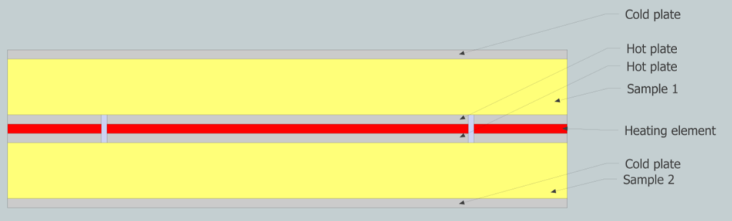
Guarded hot plate: The principle is to use 2 identical samples and to submit them to a 1D flow in a measurement zone surrounded by a guard zone. The samples are generally square. The advantage of having 2 identical samples is to avoid a thermal guard at the back of the hot surface. With the fluxmetric method, only one sample can be used.
The measurement and guard zones are separated by a gap. A table from the NF EN 12664 standard gives an order of magnitude for the dimensioning of the measuring device.
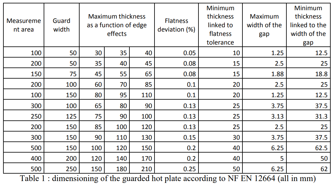
Table 1 : dimensioning of the guarded hot plate according to NF EN 12664 (all in mm)
This method has a variant which is called the fluxmetric method which consists in measuring the flow 1D. This method makes it possible to avoid the guard zones and makes it possible to have only one sample.
Standards concerning the guarded hot plate method:
NF EN 12939: Thermal performance of building materials and products – Determination of thermal resistance by the guarded hot plate method and the fluxmetric method – Thick products of high and medium thermal resistance
XP CEN / TS 15548-1: Thermal insulating products for building equipment and industrial installations – Determination of thermal resistance by the hot plate method – Part 1: high temperature measurements between 100 ° C and 850 ° C
NF EN 12664: Thermal performance of building materials and products – Determination of thermal resistance by the guarded hot plate method and the fluxmetric method – Dry and wet products of medium and low thermal resistance
NF EN 12667 (2001-07- 01): Thermal performance of building materials and products – Determination of thermal resistance by the guarded hot plate method and the fluxmetric method – Products of high and medium thermal resistance
NF X10-021 (1972-12-01): Weakly conductive materials – Determination of thermal conductivity Guarded hot plate method with samples symmetrical
EN 12939 (2001-03-01): Title: Thermal performance of building materials and products – Determination of thermal resistance by the guarded hot plate method and the fluxmetric method – Thick products with high and medium thermal resistance
ISO10291: 1994 (1994-09-15): Glass in construction. Determination of the thermal transmission coefficient U, in stationary regime of multiple glazing. Keep hot plate method.
ISO 8302: 1991 (1991-08-01): Thermal insulation. Determination of thermal resistance and related properties in steady state. Keep hot plate method.
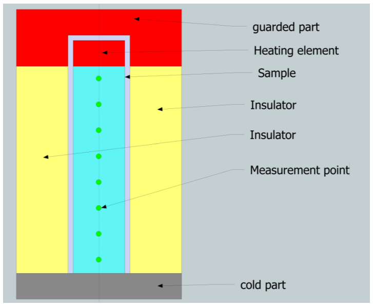
Guarded bar method
The device is identical in principle to the guarded hot plate method. Only the geometry differs.
This method is suitable for highly conductive materials such as metals. The following figure shows this type of device. The bar is heated by a heating element. Its power is precisely measured. The heat flow is therefore known precisely. The lateral heat exchanges are limited by an insulating material undergoing the same temperature gradient. At each altitude of the bar, the insulator is at the same temperature as the sample. This method is used even at high temperatures. This remains a reference method in metrology laboratories such as the NMI (National Metrologic Institute). The temperature is measured at several points. The interest is twofold:
- You can have conductivity at several temperatures if the gradient is large.
- We can correct the thermal model if however there are lateral losses.
Measurement of the conductivity in unsteady state :
The principle is to put in unsteady state that is to say in transient state. In these methods one may be led to no longer measure the conductivity alone but rather the diffusivity. This also requires mass heat to be measured by another method.
Flash method :
This method is very useful for measuring thermal conductivity on small samples.
It is essential for measuring thermal conductivity at high temperatures where temperature measurement by contact pyrometry is ineffective. This method does not require precise temperature measurement. However, we can only measure the diffusivity :
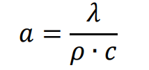
Where λ is the conductivity, at the diffusivity, ρ the density and c the mass heat.
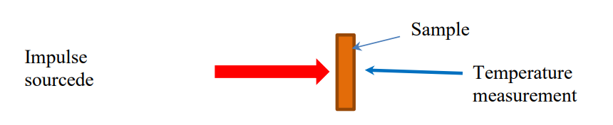
The diagram of the experimental device is presented below. It is heated by a light flash, a laser or an ion bombardment. The temperature rise is measured on the other side by pyrometry.
The principle then consists in analyzing the thermogram (temperature rise on the rear face) to determine the diffusivity :
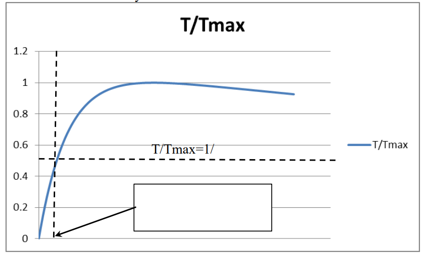
Thermogram on the rear face as a function of time:
The decrease after obtaining Tmax is due to the non-adiabatic nature of the experiment.
The simplest method is to determine the time necessary 〖 t〗_(1/2) to obtain an increase of half of the maximum increase in temperature (in the case of an adiabatic system). The diffusivity is obtained as follows :
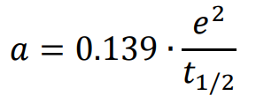
e is the thickness of the sample
The difficulties of this method are the correct dimensioning of the thickness of the sample and the choice of the flash power .
Another difficulty is to implement the right model in the case of high temperature heat exchanges preventing the use of the simplified model above.
Bibliographic point:
Measurement of thermal diffusivity by the flash method (engineering technique)
Author (s): Bruno HAY, Jean-Rémy FILTZ, Jean-Christophe BATSALE
Summary:
The flash method is the method of measuring thermal diffusivity the best known and most used. Since its development in 1961, it has been the subject of numerous developments. As a laboratory method, it is increasingly considered as an industrial control tool, due to its simplicity of implementation. This article presents the different aspects of this method, from modeling and estimation of parameters to measurement, through some examples of industrial and laboratory achievements.
Flash method standards:
NF EN ISO 22007-4 (2017-08-02): Plastics – Determination of thermal conductivity and thermal diffusivity – Part 4: laser flash method
NF EN 821-2 (1997-08-01) : Advanced technical ceramics – Monolithic ceramics – Thermo-physical properties. Part 2: Determination of thermal diffusivity by the laser flash method (or heat pulse)
ISO 13826:2013 (2013-01-15) : Metallic and other inorganic coatings – Determination of thermal diffusivity of ceramic coatings obtained by thermal spraying bylaser flash method
ISO 18755:2005 (2005-03-15) : Technical ceramics – Determination of thermal diffusivity of monolithic ceramics bylaser flash method
ISO 19629:2018 (2018-08-01) : Technical ceramics – Thermophysical properties of ceramic composites – Determination of one-dimensional thermal diffusivity by the flash method
Hot wire method:
This method is mainly used to measure the thermal conductivity of fluids, high temperature insulating refractory materials and loose insulating materials.
A resistive wire is used as a heating source. The wire (generally in platinum) also serves as a temperature sensor. We apply a power step and the study of the thermogram makes it possible to determine the conductivity. The device is shown below:
The wire (C) is heated by a 4-wire system which makes it possible to control the power and measure its resistance. The voltage and the current applied to it are recorded. we can determine the temperature of the wire
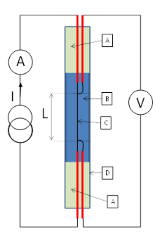
Diagram of the measuring cell
We assume a heat transfer in the fluid in cylindrical geometry in a semi-infinite medium. The measurement must be carried out for a short period in fluids so as not to suffer the effects of convection. It is also considered that the initial temperature of the wire T(0) and the electrical power P supply are constant. The resolution of the heat equation for these conditions makes it possible to obtain an analytical expression of the time evolution T(t) of the temperature of the heating wire. If a very fine heating wire is used, its inertia has a measurable manifestation on the temperature curve only at very short times. We obtain a simplified expression of the temperature variation of the wire :
![]()
Where α is the slope of the linear portion of the temperature plot relative to the logarithm of time :
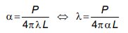
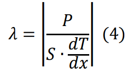
The value of α is obtained by linear regression. Equation (2) allows the calculation of the thermal conductivity of the liquid λ from the value of α experimentally determined and knowledge of the length of the wire L and the electrical power P. The constant parameter C of equation (1) also depends on the contact resistance between the wire and the liquid, the radius of the wire and the thermal diffusivity of the liquid. The values of this parameter are generally not analyzed.
A similar method has been used by NIST for thermal conductivity measurements of liquids. This method uses two wires of different lengths placed on two branches of a Wheatstone bridge to eliminate side effects.
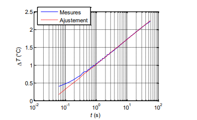
Example of a recorded thermogram allowing thermal conductivity to be obtained
Bibliographic point:
- [1] B. Le Neindre, Measurement of the thermal conductivity of liquids and gases, Engineering techniques, R2920-V2 (1996).
- Norme ASTM D 5930, Standard test method for thermal conductivity of plastics by means of a transient line-source technique (January 2009).
- [3] HM. Roder, A transient hot-wire thermal conductivity apparatus for fluids, Journal of research of the National Bureau of Standards, Vol. 86, No 5, pp. 457-493 (1981).
Standards for the hot wire method:
NF EN 993-15 (2005-10-01): Test methods for dense shaped refractory products – Part 15: determination of thermal conductivity by the hot wire (parallel) method
NF EN ISO 8894-1 (2010-08-01) : Refractory materials – Determination of thermal conductivity – Part 1: Hot wire methods (« cross » and « resistance thermometer »)
ISO 8894-2:2007 (2007-12-15) : Refractory materials – Determination of thermal conductivity – Part 2: hot wire method (parallel)
EN ISO 8894-1 (2010-08-01) : Refractory materials – Determination of thermal conductivity – Part 1: Wire methods hot (« cross » and « resistance thermometer »)
NF EN 993-15 (2005-10-01) : Test methods for dense shaped refractory products – Part 15: determination of thermal conductivity by the hot wire method ( parallel)
XP CEN/TS 15658 (2007-11-01) : Tecceramics advanced techniques – Mechanical properties of ceramic fibers at high temperature in a non-reactive environment – Determination of creep behavior by the hot jaw methoddes mors chauds
Our team is available to give you expert help and advice