Technological implementation of pyrometry
Posté le 31 March 2022 dans News
Optical pyrometry is used when the temperature is too high to allow conventional measurement (Pt100 or thermocouples) or when it is impossible to use contact measurement (moving object).
For non-contact thermometry, there are currently two different types of devices: devices with a single measurement point commonly called optical pyrometers and mainly matrix imagers but which also exist in a linear version.
main Features
The main technical characteristics to take into account are the following:
- Spatial resolution: this depends on the focus and the distance at which the target is located. This must be
smaller than the measuring spot. The optical constitution generally imposes a spot which increases with the
aimed distance. Manufacturers generally give the ratio between distance and target diameter (for example
15:1) - Precision and resolution: the data sheets indicate the measurement precision. The uncertainty includes the
precision of the device and the uncertainty due to the experimental conditions. It should therefore be
considered that precision is the lowest uncertainty that can be obtained in the measurement process. A poorly
chosen pyrometer may have an uncertainty that is too high for certain experimental conditions, while a less
precise pyrometer will have a lower uncertainty because it is more suited to the experimental conditions in
question. - The spectral band: this is strongly linked to the desired measurement temperature range. Table 1 gives an
indication of the wavelengths to be used. - The number of channels: this is the number of spectral bands used. The vast majority of pyrometers are
monochromatic, that is to say with a single channel. Broadband (total radiation) single channel pyrometers
are also available. The latter are quite sensitive and especially used when the black body hypothesis is valid
(aiming at an oven behaving like a black body). There are also so-called bichromatic pyrometers which have
the advantage of being able to overcome atmospheric transmission (smoke, particles, on the path of the
measuring beam). The specificity of these devices will be seen later. - Response time: this element must be taken into account when it is necessary to measure rapid variations. This
is often the case for detecting defects on moving materials (plastic films, rolling mill sheets, flat glass, etc.).
This generally excludes total flux pyrometers using either thermopiles or pyroelectric detectors which are
generally quite slow (bandwidth less than a few Hertz). - Operating temperature: this element is a potential source of error or bias. In fact, pyrometers are all the more
accurate and the measurement repeatable when their temperature is close to ambient and stable. For this, manufacturers usually offer optional cooled protective boxes with a suitable infrared window. This element should not be overlooked in an industrial environment - Interfaces:this element is not to be neglected either. Indeed, a transmission in the form of an analog signal
can be comfortable, however its transmission in a disturbed environment can lead to additional uncertainty.
Manufacturers offer many digital interfaces (serial, I2C, USB, RS232, RS485, Profibus , Ethernet, etc.) adapted
to current control systems.
| Pyrometer wavelength (µm) | Pyrometer temperature range |
| 0.65 | > 1000°C |
| 0.7-1.1 | 700°C to 1800°C |
| 1.6 | 250°C to 1800°C |
| 2.3 | 200°C to 1500°C |
| 5 | 100°C to 1800°C |
| 7.9 | 0°C to 1000°C |
| 8-14 | -40 to 1000°C |
Tableau 1. Indicative temperature range for the use of pyrometers depending on its wavelength.The measurement is all the more precise when the shortest wavelength is used.
Construction of a pyrometer
A pyrometer consists of focusing optics adapted to the spectral band used (figure 1). This forms the image of thetarget area on the detector. The detector is adapted to the spectral band used. This configuration allows anoptimal measurement at a given distance. The configuration is chosen according to the distance from the target.The pyrometer can be used at distances other than the nominal distance, however the measurement spot (usefulmeasurement area) will be larger than at the nominal distance. Manufacturers generally give the ratio betweendistance and target diameter (for example 15:1).
The detector gives a quantum signal (counting of photons) or a pyrometric signal (measurement of the powerreceived by the detector). In the case of pyrometric detectors (thermopile or pyroelectric detectors ) , the signaldepends on the temperature of the target area and the internal temperature of the pyrometer. To correct this, thetemperature inside the pyrometer is measured in order to correct the measurement temperature. This is one ofthe main sources of measurement bias. Some pyrometers use a chopper (allowing alternate targeting of thetemperature of the measurement zone and an internal reference temperature) in order to better overcome this bias.
An important variant exists consisting of separating the focusing optics from the electronics by means of an optical fiber link. This makes it possible to place the measurement head, which is not very sensitive to heat, close to the area to be measured and to place the detector and the conditioning electronics away from the heat (figure 2).

The constitution of the bi-chromatic pyrometers is similar to the monochromatic pyrometer with the possibility of measuring two different spectral bands.
Principle:
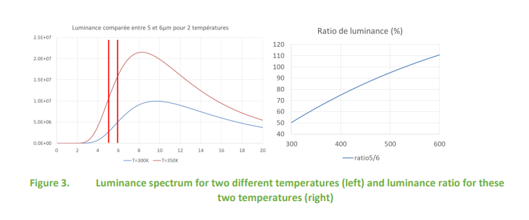
At first, we will consider the gray body hypothesis as valid. On figure 3 on the left one can see the luminance inW/m 3 at two temperatures. It can be seen that the ratio between these two luminances varies according to thetemperature (figure 3 on the right). If the emissivity is the same at these two wavelengths (grey body hypothesis)this ratio makes it possible to deduce the temperature of the material with good precision. In addition, in the eventof degraded transmission (vapour, particles, etc.) or measurement through a protection window, this ratio will not be affected.
What if the body is not grey?
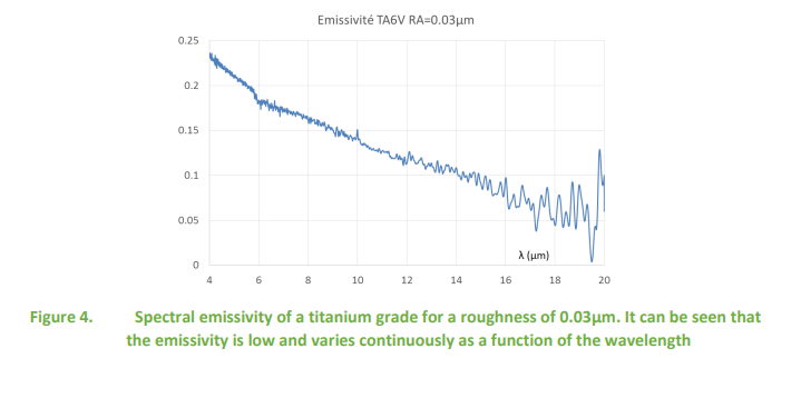
Most industrial measurements are made on known materials. We can take as an example the case of titanium. This
one is not gray (figure 4). Manufacturers of bichromatic pyrometers have found the solution: to allow the emissivity
ratio to be corrected. Two methods are possible for calibrating this ratio: the spectral emissivity is known (as in the
case of titanium); the pyrometer is calibrated by targeting a surface identical to the target material of known
temperature (measured with a contact thermocouple for example) and the emissivity ratio is adjusted until the
correct temperature is obtained.
bichromatic pyrometry used ?
Bichromatic pyrometry is widely used in processes where the emissivity can vary from a low level to high values (in
metallurgy for example where metals can be oxidized randomly). This method is also widely used when the air is
loaded with particles or vapor that significantly weaken atmospheric transmission.
Measurement with a monochromatic pyrometer (by luminance measurement)
The principle is to measure the luminance in a single spectral band. The causes of uncertainty can be numerous:
- Optical path attenuating the measurement beam (dirty optics, atmospheric absorption, smoke and dust on the optical path, etc.)
- Ignorance or variability of emissivity
- Disturbed radiative environment
Table 2 shows an example of calculation of the errors made for a temperature measurement close to the ambient temperature. Errors increase with temperature.
Luminance pyrometry is however widely used in industry because it is a simple and inexpensive method. In addition, it is effective if the emissivity is well known; which is the case in many applications.
| Error source | Error on temperature measurement |
| 1% error on emissivity value | 0.75K |
| Error of 10K on environment temperature | 1K |
| 10m transmittance band III (8-12µm) | 1.5K |
| 10m transmittance band II (3-5µm) | 5.6K |
Tableau 2. quantification of the errors made according to the sources of error for a measurement at room temperature (band III corresponds to the 8-14 µm band) on an emissivity surface of 0.9.
Characteristics of thermal cameras
There are two main categories of detector for thermal cameras:
- Quantum detectors for which the measurement signal is proportional to the number of photons that hit the detector. These detectors are cooled (most of the time to -196°C by a Stirling type thermal machine). These detectors are very sensitive but the cameras using this technology are quite expensive. They are reserved for specific applications or in R&D.
- Thermal detectors called micro-bolometric. These thermal detectors measure the heating of each pixel subjected to thermal radiation. These sensors are much less expensive than the previous ones but require fairly advanced signal processing in order to extract a thermal image. The vast majority of cameras used in industry use this type of sensor. Their spectral band is in the 8-14µm band.
Thermal imagers are mostly made with matrix sensors. These are the ones that will be described later. However, linear array or single detector sensors cannot be overlooked. For the former, the image is constructed by recording each line of the area of interest either by moving relative to the subject (aerial thermography) or by measuring a subject moving relative to the camera. This is very often the case for plastic films, rolling mill sheets or any type of manufactured product in strip form which can pass in front of the camera lens.
For single-detector imagers, a mirror scans a line and moving the camera relative to the target area provides
scanning in the other dimension. This is the device generally used in aerial thermography. - The temperature range: this is the main characteristic and it is the application that will dictate which camera to choose.
- The resolution: it is the number of pixels of the sensor matrix. This usually ranges from 80×64 to 1024×868. This may change as technology advances.
- The optics: the optics condition several properties. The field seen by the camera very often called the FOV (Field Of View ). It is an angular data it can go from 6°x5° for a telephoto lens to 72°x52° for a wide angle. We do not go beyond this angle because beyond 45° of incidence the directional emissivity drops and makes the measurement very inaccurate. The other optical characteristic is the spatial resolution. This data is often given in mrad (this ranges from 15mrad for a wide angle with low resolution to 0.1 mrad for a camera with a telephoto lens and high resolution.
- Measurement accuracy: it is rarely less than 2°C or +/-2% for industrial cameras. However, thermal cameras are very efficient in detecting small spatial variations in temperature.
- NETD (Noise Equivalent Temperature Difference ): it is the noise of the measurement chain given in temperature equivalent. This measurement noise varies from a few mK to 0.3K depending on the type of camera.
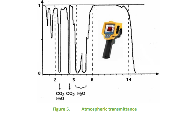
- The spectral range: it depends on the sensor. For bolometric sensors the spectral band is in the 8 to 14 µm band. Cooled cameras can work in this band or in the 3 to 5 µm band. The two bands mentioned correspond to the transparency bands of the atmosphere (Figure 5).
For matrix cameras here are the main characteristics:
Thermal cameras and luminance pyrometer, how to optimize measurements?
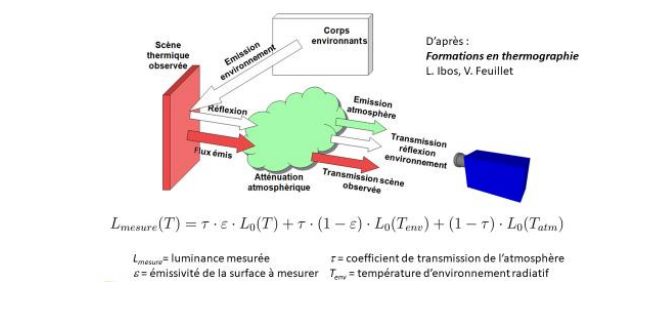
The luminance seen by a pyrometer or a thermal camera is represented in figure 6. This figure as well as the literal expression of the luminance seen by the detector make it possible to carry out a measurement correction by calculation, on condition of knowing the emissivity as well as the radiative environment temperature. Otherwise, this expression is used to calculate the uncertainty. To avoid any measurement bias, a situation is generally put in which the optical path is transparent. However, the question of emissivity remains central in optical pyrometry.
Table 3 gives some examples of emissivity values.
How to overcome emissivity?
Cover the target with a highly emissive coating:
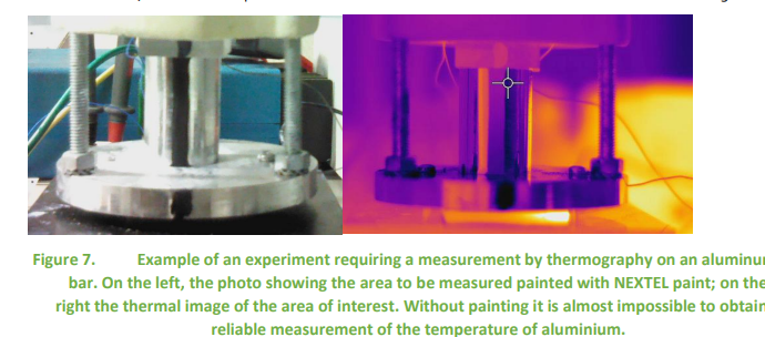
The simplest solution, if the target allows it, is to cover the surface to be measured with a paint of known emissivity (example in figure 7). This can be standard or polyimide tape for temperatures up to 400°C. commercial paints can do the trick (acrylic or glycerophthalic). Commercial high-temperature paints can also be used (stovepipe or “barbecue” paint). For more specialized applications there are more suitable paints:
- NEXTEL Velvet Coating 3M paint is a reference paint because it is a black paint with an emissivity of 0.97, which is very high. In addition, its spectral emissivity is constant from ultraviolet to far infrared.
- AREMCO paint whose references (840 C, CX, M, MX) define the target surfaces (ceramic or metal) and the temperature limit (1093 or 1316°C). They are widely used to determine the surface temperature in industrial processes. They have a spectral emissivity which is not constant and an emissivity value around 0.85.
- LAB-IR ( https://labir.eu/ ) offers a complete range of emissive paint for thermography, less efficient than NEXTEL, but much cheaper and available in a water-washable version for non-destructive testing.
Create an emissive cavity:
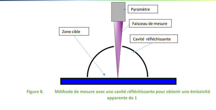
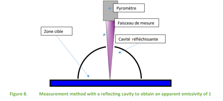
If the surface to be measured is surrounded by a reflecting cavity (almost zero emissivity), the resulting apparent emissivity will be close to 1. In fact, the multiple reflections will be added. The diagram in Figure 8 shows how to do this. This method makes it possible to obtain very good measurements with a luminance pyrometer on different types of supports (sheet metal, plastic film, bulk products on a conveyor belt, etc.)
Determine emissivity:
Table 3 gives an idea of the emissivity values encountered in the different types of applications.
| Polished aluminum | 0.05 |
| Anodized aluminum | 0.60 |
| polished brass | 0.03 |
| Oxidized brass | 0.61 |
| polished copper | 0.05 |
| Oxidized copper | 0.78 |
| polished gold | 0.02 |
| polished cast iron | 0.21 |
| Oxidized cast iron | 0.64 |
| Very rusty cast iron | 0.69 |
| Polished nickel | 0.05 |
| Polished nickel | 0.37 |
| polished silver | 0.03 |
| Polished stainless steel | 0.16 |
| Oxidized steel | 0.85 |
| Polished steel | 0.07 |
| Tin | 0.07 |
| Red brick | 0.93 |
| Carbon – carbon black | 0.95 |
| Carbon – graphite | 0.98 |
| Glass | 0.92 |
| Concrete | 0.92 |
| matte black paint | 0.97 |
| Wood | 0.90 |
| Nickel | 0.05 |
| Glycerophthalic paint | 0.94 |
| Paper | 0.93 |
| Plaster | 0.91 |
| Sand | 0.90 |
| human skin | 0.98 |
| dry land | 0.92 |
| wet earth | 0.95 |
| Distilled water | 0.96 |
| Ice | 0.96 |
| Snow | 0.85 |
Tableau 3. Indicative values of emissivity of different materials. These values do not take into account the spectral band. Notable differences may exist depending on the type of materials and their surface condition.
Specialized laboratories are able to measure the directional emissivity in the useful band. The other possibility, less precise but very useful because it can be used in the field without taking a sample, is that described in the ISO6781 standard. This determination method is essential in infrared thermography and is described below.
In order to measure the emissivity of the target, the following equipment is required:
- The camera used
- A natural or induced means of heating the target to at least 20°C above the reflected apparent temperature (radiative environment temperature)
- A contact thermometer or surface modifying material such as paint or tape with a known high emissivity in the spectral band of the camera
Method with a contact temperature sensor:
- place the thermal camera at the desired location and distance from the target to be measured;
- measure and compensate for the reflected apparent temperature of the target (radiative environment temperature);
- aim and focus the thermal camera on the target and, if possible, freeze the image;
- use an appropriate camera measurement function (such as spot temperature, crosshairs, or isotherms) to define a measurement point or area at the center of the camera image;
- use a contact thermometer to measure the temperature of the point or area which has just been defined by the measurement function of the camera. Note this temperature;
- without moving the camera, adjust the emissivity control until the indicated temperature is the same as the contact temperature. The emissivity value indicated is the emissivity of this target temperature measured with this camera;
- for greater accuracy, repeat procedures b) to f) at least three times and average the emissivity
- compensate the emissivity by entering the average emissivity value in the IRT camera under the emissivity input.
The emissive reference material method is as follows:
- place the thermal camera at the desired location and distance from the target to be measured. Aim the target;
- measuring and compensating for the apparent temperature reflected from the target;
- apply the surface modifying material on or immediately adjacent to the target you are measuring. Ensure that the surface modifying material is dry and/or in good contact with the target;
- enter the known emissivity of the surface modifying material into the emissivity entry;
- aim and focus the thermal camera on the material modifying the surface, allow sufficient time for the temperatures to stabilize, freeze the image, measure and record the indicated temperature;
- Aim and focus the thermal camera at the target immediately adjacent to the surface modifying material, and aim and focus the camera at the previously modified surface.
- Be sure to allow enough time for the temperature to stabilize, freeze the image, measure and record the indicated temperature.
- Using the frozen image, adjust the emissivity control until the indicated temperature is the same as the noncontact temperature of the surface modifying material. The emissivity value indicated is the emissivity of this target temperature measured with this camera;
- for greater accuracy, repeat procedures b) to g) at least three times and average the emissivity
- compensate the emissivity by entering the average emissivity value in the thermal camera on the emissivity input of the camera.
This method comes from the ISO 6781-1 standard. It may vary depending on the camera options available. Since the temperature of the radiative environment can vary during the measurements, there is a method for evaluating the temperature of the radiative environment consisting of placing a very low emissivity and diffusing surface (typically crumpled aluminum foil) in the field of the camera. The temperature measured by aiming at this surface with the camera is that of the radiative environment. Care will be taken to ensure that this diffusing mirror is at a temperature close to the environment temperature. If this is not possible (a clear sky and clear environment can give a radiative environment temperature of -50°C), a correction calculation is necessary.
Examples of pyrometers and cameras
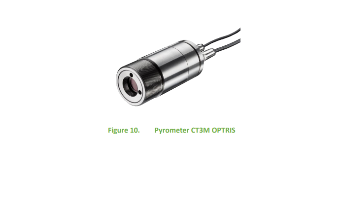
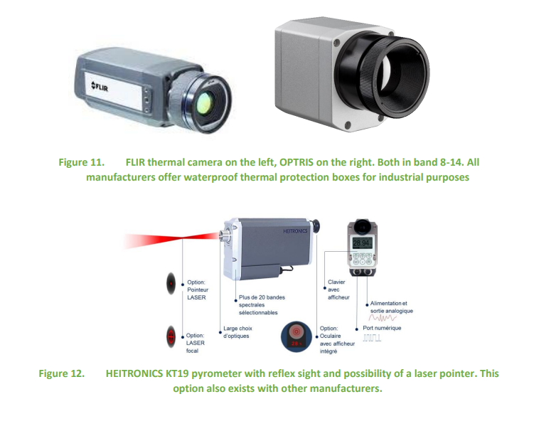
We present here examples of cameras and pyrometers, with a non-exhaustive list of manufacturers and distributors.
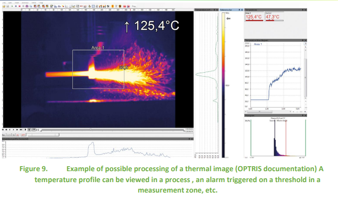
Figures 9 to 12 illustrate industrial supply.
Here are some examples of pyrometers:
- The range of OPTRIS pyrometers is quite varied and the computer configuration tools quite easy to use. OPTRIS also provides industrial thermal cameras with a very comprehensive software package for configuring alarms and data recording.
- Heitronics provides premium pyrometers. The metrological quality is irreproachable but at a cost of around 4 to 6 times higher than its competitors.
- Flir and Fluke are two of many thermal imaging camera providers
- KELLER HCW GmbH is another European pyrometer manufacturer
This list is far from exhaustive and search engines on the internet bring up a multitude of devices.
For further
Engineering techniques:
Optical pyrometry r2610 by François CABANNES
Surface temperature pyrometry: Radiative measurements r2735 by François CABANNES
Thermography – Principles and measurement r2740 by Dominique PAJANI
Thermography – Technologies and applications r2741by Dominique PAJANI and Luc AUDAIRE
Measurement of thermal emissivity r2747 by Jean-Pierre MONCHAU, Jacques HAMEURY
Standards:
Standard NF-EN-ISO 6781-1 to -3 Performance of buildings – Detection of heat, air and humidity irregularities in
buildings by infrared methods is the one that provides the most technical information on measurement by
thermography even if the standard is oriented towards the thermal of the building.
ASTM E639-78(2002) Standard Test Method for Measuring Total-Radiance Temperature of Heated Surfaces
Using a Radiation Pyrometer
ASTM E1256-17 Standard Test Methods for Radiation Thermometers (Single Waveband Type)
