Thermal emissivity Measurement
Thermal emissivity Measurement
1. 1 Different emissivities
The material surfaces can exchange energy in form of radiation. The amount of energy that a surface can emit depends on its temperature and its nature. Planck’s law specifies the spectral energy luminance for a theoretical surface called the black body:

where h = 6.62617.10−34 Js is the Planck constant, c the speed of light in the medium considered (we will take the value of c in a vacuum: c = 299792458m.s − 1) and k = 1.38066.10−23 JK −1 the Boltzmann constant. The spectral energy luminance L0 is expressed in Wm-3.sr-1.
For a given material, this luminance is weighted by a coefficient between 0 and 1 and called emissivity. We write it ε.
This coefficient can depend on the wavelength, the incidence and the temperature: ε(λ,T,θ,φ).
Emissivities are classified according to the spatial and spectral domains of the radiation. We call total emissivity the emissivity calculated over the whole spectrum and monochromatic emissivity the emissivity calculated for a single wavelength. We call hemispherical emissivity the emissivity calculated for all directions and directional emissivity that calculated in one direction.
1.1 Directional monochromatic emissivity
Directional monochromatic emissivity noted ε_λ^| is the ratio between the luminance of the material and that of the black body for a given direction and wavelength. It is the quantity which allows the finest description for a given material:

L0 does not depend on the incidence for a black body.
Most materials have an emissivity which does not depend on the orientation and therefore does not depend on ϕ.
For smooth surfaces this emissivity may depend on the polarization of the light.
1.3 Total directional emissivity
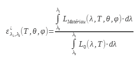
The total directional emissivity is the ratio between the luminance radiated by the surface of the material studied by the luminance radiated by the black body over the entire electromagnetic spectrum:

This value of the emissivity interests users of thermal cameras. Indeed, it makes it possible to connect the luminance in a direction with the temperature. This calculation or this measurement of emissivity can be done in a wavelength band identical to that of the camera or in a given spectral band:
1.4 Total hemispherical emissivity
The total hemispherical emissivity noted ε is the ratio between the total hemispherical emittance of the material by that of the black body for all the wavelengths at a given temperature:

It is this emissivity that interests thermicians to carry out thermal balances of opaque walls. It makes it possible to calculate the radiative exchanges of a surface brought to the temperature T
1.5 Special cases
If the emissivity of a material does not depend on the wavelength, one qualifies this one of gray body. This property is not encountered in reality and we will qualify as a gray body, a body for which the emissivity does not vary in the spectral domain studied. A gray body whose spectral properties do not vary as a function of temperature has an emissivity which does not vary as a function of temperature either. Conversely, a surface having a spectral emissivity varying with the wavelength will have a total emissivity varying with temperature, since the black body radiation spectrum varies with temperature.
As we have just seen, the emissivity of a real material generally also depends on the emission angle. It is therefore not a Lambertian surface. For dielectrics, however, the emissivity varies little over a wide angular range (from 0 to 60◦). In this angular domain, they are considered Lambertians. Figure 1 from (1) shows the total directional emissivity as a function of the angle for a number of materials. We can see that it does not vary up to an angle of 60◦. In addition, the law of variation of the emissivity as a function of the angle shows a similarity in shape.
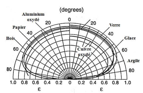
Figure 1
Total directional emissivity as a function of direction from (1)
2.Calculation of emissivity from the complex index
The law of conservation of energy is expressed in the case of electromagnetic radiation by Kirchhoff’s law . In the general case, this law links for a given wavelength the transmission factor, the hemispherical directional reflection factor to the absorption which is in this case equal to the emissivity

Where a is the spectral absorption factor, τ the spectral transmission factor and ρ the hemispherical directional reflection factor.
For an opaque material this relation becomes

Since ε = a and that for an opaque material τ = 0.
Equation (8) is the basis of all indirect methods of measuring emissivity. It also makes it possible to calculate the emissivity from the reflection factor itself calculated by Fresnel relations. This approach is only valid for diopters, that is to say for smooth surfaces.
1.6 Calculation of the emissivity for the two polarizations of light
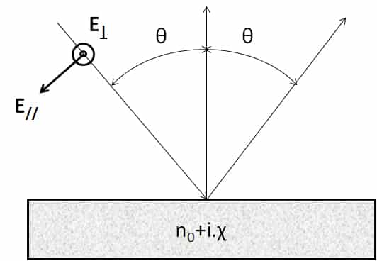
For the planar diopter, one can calculate the emissivity from the expression of the reflection coefficients, calculated from the complex index, n = n0+ i. χ. This detailed calculation can be found in (2) from Maxwell’s equations. These expressions are deduced from the Fresnel coefficients for reflection, they can be found in (3). Equations 9 and 10 can be used with complex indices which allows them to be used for the calculation of the emissivity of metals. Considerations of boundary conditions at the level of the diopter make it necessary to calculate a coefficient of reflection and therefore of emissivity for two distinct polarizations. These polarizations are explained in the diagram in Figure 2
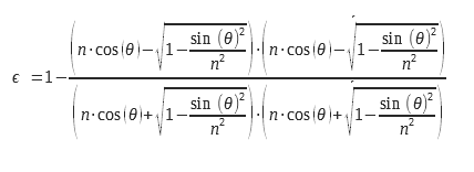
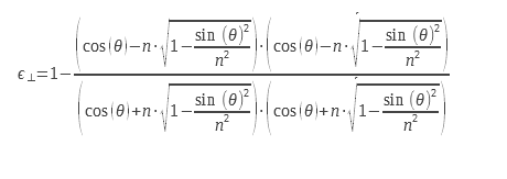
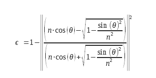
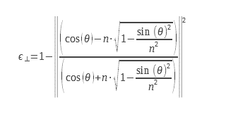
For non-polarized light, we must perform the arithmetic mean of the two emissivities corresponding to the two polarizations. The expressions of the two emissivities for the two polarizations are presented below:
We can write them in another form:
1.7 Case of dielectrics
Figure 3 from (2) shows the directional emissivity as a function of the angle for a dielectric with a refractive index of 1.5: this corresponds to a relative dielectric permittivity of 2.25:
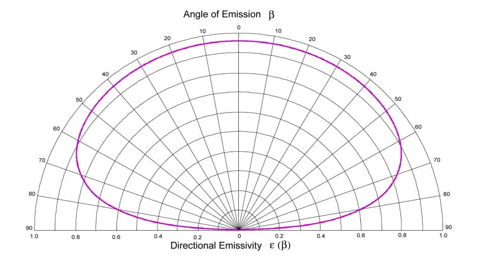
Figure 3
Directional emissivity as a function of the angle for a dielectric with a refractive index of 1.5 (2)
These are typically the characteristics of a glass based on boro-silicates. We note that we find the same form of emissivity indicator by theory as those measured experimentally (Figure 1). Since the only parameter that can vary the emissivity of a smooth dielectric diopter is the real refractive index, for a given refractive index, we will always have the same emissivity indicator. Therefore, one can calculate by integration on the whole of the hemisphere the hemispherical emissivity.
The relationship between hemispherical emissivity and normal directional emissivity is therefore only a function of the refractive index, and therefore only of normal directional emissivity (Figure 1). We can therefore deduce the hemispherical emissivity from normal directional emissivity, and vice versa. These reports are tabulated in standard NF EN 12898 concerning the determination of emissivity for building glass. This study can be used for a non-smooth dielectric with a good approximation. In fact, the rough character has very little effect on the emissivity indicator of a dielectric. These considerations will be taken up in section 2.4.
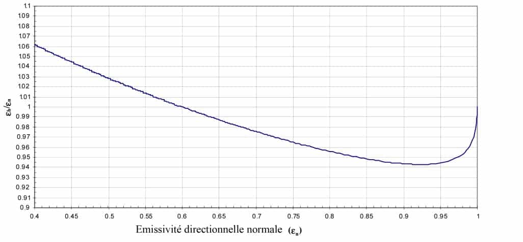
Figure 4
Relationship between hemispherical emissivity and normal directional emissivity as a function of normal directional emissivity for smooth dielectrics (2)
1.8 Case of metals and conductors
In the same way, we can plot the emissivity indicator for a air / metal diopter. A theoretical emissivity indicator similar to that which can be obtained on a metal such as aluminum is obtained. The one shown in Figure 5 from (2) is calculated for a refractive index typical of a metal such as aluminum: n = 5.7 + 9.7i. The correspondence between hemispherical emissivity and normal directional emissivity also exists for drivers, however the emissivity indicator is different.
It is therefore necessary to treat the conductors separately from the dielectrics to determine the relationship between the two emissivities. This study cannot be used for a non-smooth conductor. Indeed the rough character strongly affects the emissivity indicator of a metal because the emissivity of a metal varies a lot with the roughness of this one. We will refer to [30] for a more detailed study of the emissivity of metals as a function of roughness.
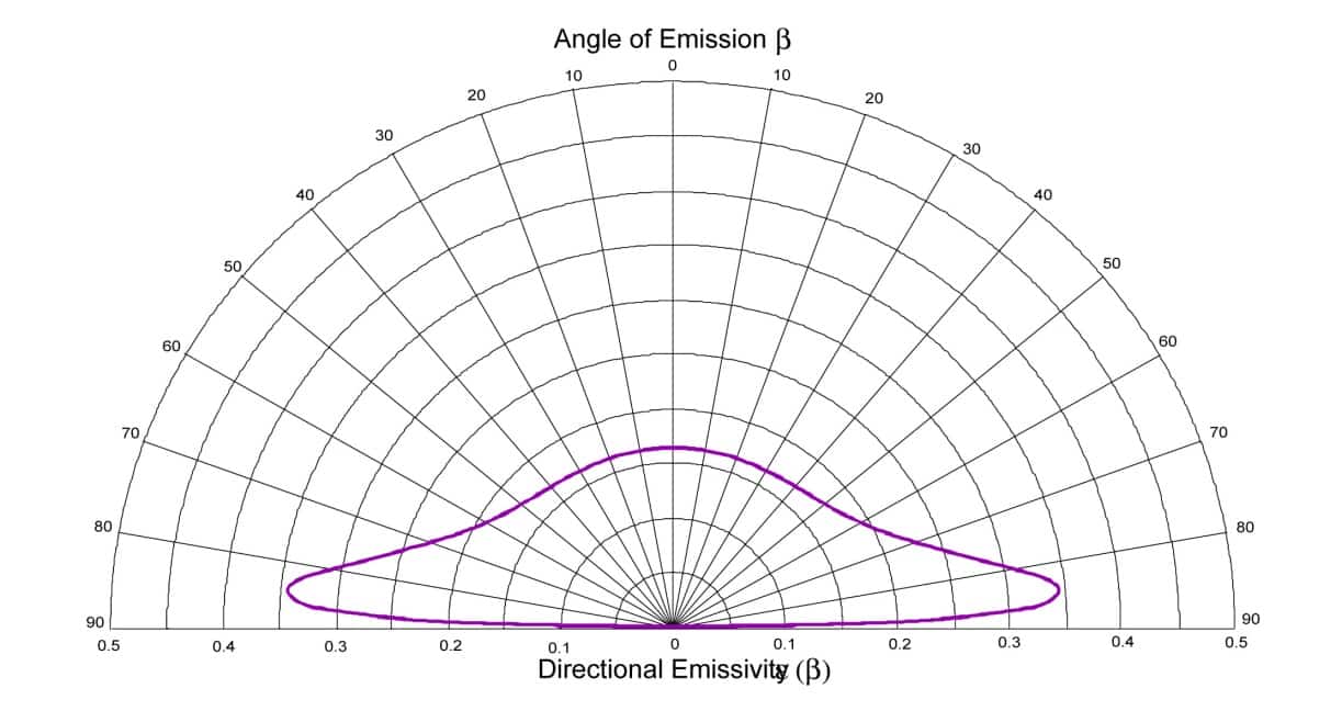
Figure 5
Directional emissivity as a function of the angle for a metal with a refractive index: n = 5.7 + 9.7. i
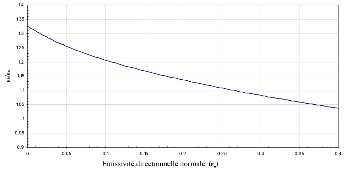
Figure 6
Relationship between hemispherical emissivity and normal directional emissivity as a function of normal directional emissivity for smooth conductors (2)
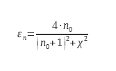
For conductors, two parameters, n0 and χ can vary. Figure 6 shows a theoretical curve obtained by varying the imaginary part of the index. For more complex cases and especially for rough surfaces, experimental studies have made it possible to tabulate values
1.9 Relation between the normal directional emissivity and the hemispherical emissivity
One frequently measures for questions of ease the directional emissivity in almost normal incidence. However, it is often necessary to obtain the hemispherical emissivity.
This is the integration on all useful solid angles of directional emissivity. If one cannot measure this one on the whole of the incidences one must be able to deduce the hemispherical emissivity of the directional emissivity in almost normal incidence. This calculation is theoretically possible for smooth dioptres of dielectrics because the emissivity only depends on the normal index (Figure 1). The values in Table 1 are taken from ISO standard 12898. It is intended for measuring the emissivity of glazing.
Table 1 Factors for calculating total hemispherical emissivity from εn for a smooth dielectric surface
Some remarkable studies have made it possible to document this coefficient ε∩/ εn. For smooth surfaces with low emissivity (typically metals). Rubin and Hartmann (4) used silver and Inlayers2O3 on glass. An analytical expression was obtained using experimental data and Kramer Kroning relations
For dielectrics for which the emissivity εn is between 0.68 and 0.98 another expression is used (4) (5):
These data are grouped and enriched in two European research reports (6) (7). They made it possible to provide the data necessary for the drafting of the ISO 12898 standard.
These data are plotted in Figure 7. The legendary curve Metals corresponds to equation (14), that legended Dielectric to equation (15). The values tabulated in ISO 13898 are also shown in this graph.
.
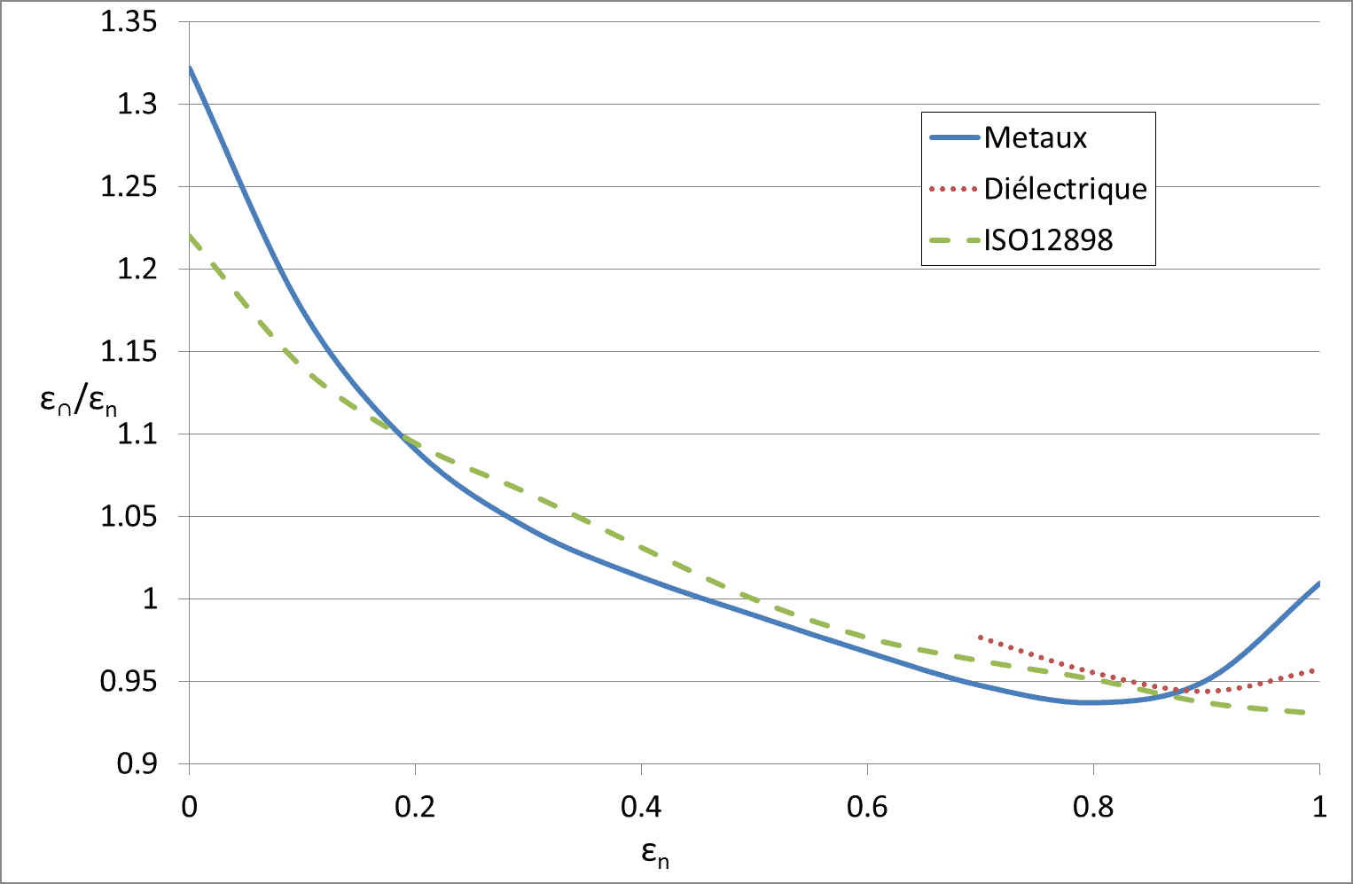
Figure 7
Relationship between ε and εn according to the different sources
3 The different methods of measuring thermal emissivity
1.10 Classification of methods
In this chapter, we discuss the methods of measuring emissivity. They have been classified according to the physical principle of measurement. We have separated the so-called direct methods from the so-called indirect methods. Direct methods are those where the power radiated by the surface is measured directly: these are calorimetric and radiometric methods.
Indirect methods are those in which the properties of surfaces in the infrared spectral range are deduced from optical properties by reflectometry: this is the case for all the other methods. All commercial devices use these indirect methods in one way or another. The direct methods are only limited by the experimental device used. Indirect methods suffer from intrinsic biases in the measurement method itself.
1.11 Calorimetric method
The method makes it possible to evaluate the radiative transfers without neglecting any incidence or any wavelength. It consists in carrying out an energy balance of the radiative losses of the studied sample when these are the only ones at stake. It is a direct and absolute method, that is to say it does not require a reference d standard emissivity to
obtain the emissivity of the sample. This method remains cumbersome. Indeed, to eliminate transfers by conduction and convection, the sample must be placed under a reduced atmosphere (typically 10−5 mbar). The sample is heated and kept at the temperature at which it is desired to know the emissivity. To maintain its temperature, we must provide it with
a power:

where P is the power dissipated by the sample, ε its emissivity, σ the Stefan constant – Boltzmann, T the temperature of the sample, εe the emissivity of the enclosure, Te the temperature of the enclosure and S the emissive surface of the sample. The power necessary to maintain the sample at the temperature at which it is desired to know the emissivity is supplied electrically in the form of the Joule effect. Figure 8 shows schematically a device for measuring emissivity by the calorimetric method. The enclosure (F) is maintained under vacuum using a pumping device connected to the enclosure by the piping A.
The electrical supply and measurement wires (B) are connected to the sample by a terminal block C. This serves as a guard to avoid losses by conduction. The temperature of this terminal block is maintained and regulated at the same temperature as the sample. In this way, the power dissipated by conduction by the electrical supply and measurement wires between the terminal block and the sample is zero due to the absence of a temperature gradient. The sample disc of known radiating surface is suspended in the enclosure. The enclosure E is a thermally insulated cryostat generally filled with liquid nitrogen. Helium is used when it is desired to measure emissivities at low temperatures (below 250K) for the space industry. Such a device is described in (8). The enclosure F is covered inside with a coating of high emissivity and spectral emissivity varying little with the wavelength. The choice of cryostat temperature is guided by the need to have ε.T4 ≫ εe.Te4. The ideal temperature should allow a bias much lower than the measurement uncertainty of the device. From relation 16, we can deduce the emissivity:

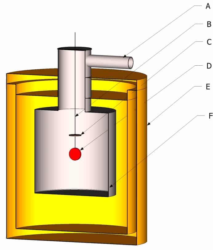
Figure 8
Schematic diagram of the calorimetric method
The calorimetric method is the only one to allow direct determination of the total hemispherical emissivity. All of the radiation is taken into account. The fact that it does not require a reference or an emissivity standard makes it a reference method. However, this method remains cumbersome and time-consuming to implement. It would be difficult to build an emissivity database with this method alone.
The main source of uncertainty is the measurement of surface temperature. This can be extrapolated by measuring the temperature gradient inside the sample using different sensors (9). In addition, it is necessary to have samples calibrated in size to fit into the measuring device. Other simpler devices are described in (10).
1.12 Radiometric method
1.1.1 Method by direct measurement of flux / luminance
This method consists in comparing the luminance of a sample with that of a black body brought to the same temperature. The device is described in Figure 9. In this figure, the sample A is brought to the temperature at which it is desired to measure the emissivity. This is placed in a cooled enclosure B with the same temperature conditions as for the calorimetric method (ε.T4 ≫ εe.Te4). A black body E brought to the same temperature as the sample is the luminance reference. The luminance of the black body and that of the sample are successively measured using the tilting mirror C. The relationship between these two luminances gives the emissivity. The black body is placed in an insulated enclosure without temperature conditions. It is possible to make the measurement with a black body having a temperature different from that of the sample. In this case a relationship between the temperatures at power 4 applies.
The two luminances are measured using the detector D. This can be a broadband infrared detector (like a thermopile) to measure the total emissivity. This detector can be fitted with a filter wheel to measure the spectral emissivity for different wavelengths (11). The set of devices for measuring emissivity by comparison with a black body from the NIST (National Institute of Standards and Technology, Gaithersburg, Maryland, United States) is presented in (12). In this device there is no tilting mirror, the detection system is moved in front of the surfaces to be measured and the reference black bodies by means of a carriage. This device is a benchmark in the field for emissivity measurements for temperatures ranging from 600K to 1400K. The emissometer described by (13) uses a Fourier transform infrared spectrometer. The luminance is therefore measured in one direction only, a directional emissivity is thus measured. To measure different incidences and go back to the hemispherical emissivity, certain devices allow the sample to rotate: this is the case of the device described in (13). The spectrometer can also be replaced by a monochromator like the device described in (14).
Radiometric measurement at room temperature requires placing the sample in a cryostat at very low temperature and under vacuum to avoid condensation. An original device avoiding this problem is described in (15). The principle remains the same, however the measurements are made at room temperature, the measured flux is then corrected from the temperature measurements of the enclosure and the chopper. This greatly simplifies the device, but introduces additional sources of uncertainty
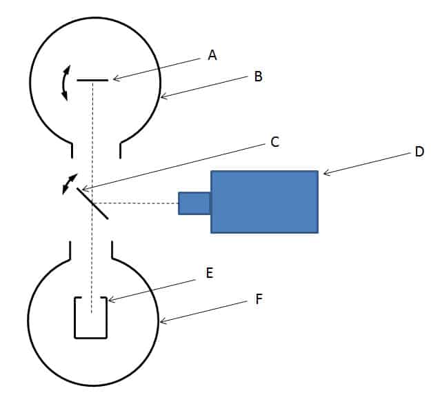
Figure 9
Radiometric method
Themethod consists in modulating the temperature of the sample slightly around the temperature where one wishes to know the emissivity. Thus, we can separate the reflected flow from the sample’s own flow. This is the principle of the modulated radiometric method.
To obtain emissivity, the measured flux must be compared to that of a known emissivity surface. Another method consists in also modulating a hemispherical source at a frequency different from the modulation frequency of the sample. By carrying out the measurement on two unknown samples, it is possible to obtain the value of the emissivity and the reflectivity. This method does not require an emissivity reference to perform the measurement. The periodic radiometric method is detailed in [20].
1.13 Reflectometric Methods
The reflectometric method consists in measuring the directional hemispherical reflection coefficient ρ^(∩ |) or the hemispherical directional reflection coefficient ρ^(| ∩ in) order to calculate the directional emissivity for a direction equivalent to that used to measure the reflection coefficient. This calculation is based on Kirchhoff’s law (2). We can state this law as follows: for an opaque surface in thermal equilibrium with its environment, we can write for a wavelength λ:

The thermal equilibrium imposes an identical temperature for the environment and for the surface in question. This relationship can be extended to a wavelength range.
This reflection coefficient can be calculated either by measuring the reflectance for all wavelengths and by carrying out the integration weighted by the emittance of the black body, or by ensuring that the reflectance is measured with a light source. having the same spectral energy distribution as the black body at the temperature considered. It must also be ensured that the infrared detector used has a sufficiently constant response in the spectral range considered. Provided that the spectral reflectance does not vary with temperature, one can calculate this reflectance without worrying about the temperature of the sample. We will see several methods of measuring emissivity from the reflectance measurement.

Figure 10
Diagram of a device for measuring hemispherical directional reflection using the integrating sphere method
1.1.3 Integrating sphere method
Figure 10 shows the operation of an integral sphere. This must be covered internally with a reflective and diffusing coating. The sample is illuminated by an infrared source in a given direction close to normal. The angle of incidence in the integrating commercial spheres is between 8 and 12 degrees. Once the light has reached the sample, it is scattered in all directions according to the reflectance indicator of the material. After multiple reflections, the light reaches the detector placed on the side. Thus the detector in theory measures almost all of the flux reflected by the sample.
A baffling system prevents the detector from directly seeing the sample so as not to disturb the measurement. A detector can be placed symmetrically at the source to measure the specular reflection. This one is optional, and on certain spheres one can put at the location of the specular reflection either a portion of diffusing surface of the same nature as the sphere, or leave it open. In the first case, the whole of the reflected flux (diffuse and specular) is measured and in the other case only the diffuse flux.
By subtraction, the specular reflection coefficient can be obtained. To perform a reflection coefficient measurement, it is necessary to calibrate the device with a reflectance reference. The same type of coating is used as that used for the sphere. It is generally a sanded metal surface covered with a layer of gold. A device of this type is used at NIST. It is described in (16).
1.1.4 Method using a modulated source
Previously, for the radiometric method, when we wanted to measure the flux emitted by the surface, we had to get rid of the flux from the radiative environment around the sample. This was therefore placed in an enclosure cooled to a temperature Te, so as to ensure σ.T4>> σ.Te4. This constraining condition is however easy to obtain thanks to a water-cooled enclosure for sample temperatures of the order of 1000K. However, when one wants to measure an emissivity at room temperature, it is necessary to cool the enclosure to cryogenic temperatures. To avoid this additional complexity, the temperature of the sample to be measured can be modulated around the temperature at which the emissivity is desired (17). In this case, the modulated flux emitted is detected and compared with a modulation amplitude equal to that emitted by a reference surface. When it is not possible to modulate the temperature of the sample, a reflectometric method can be used and the flux used to measure the reflection factor can be modulated. These methods are described in (18) and a specific example of implementation in (19).
To separate the sample’s own flow from the reflected flow, a frequency-modulated hemispherical flow is sent over it. The principle consists in producing a hemispherical infrared flux modulated around the sample studied and in measuring, in one direction, the flux reflected by the surface of the material using a thermopile. The diagram in Figure 11 shows the principle of the device. The device is calibrated beforehand using a known reference material. Figure 12 shows the diagram of the device developed at CERTES (19) as well as a photo of the instrument. The cavity consists of a hollow aluminum cube open from the bottom. The temperature of the walls is modulated using Peltier elements. The measurement of the reflected flux is made through an orifice made at the top of the device by means of a thermopile provided with a KRS5 lens.
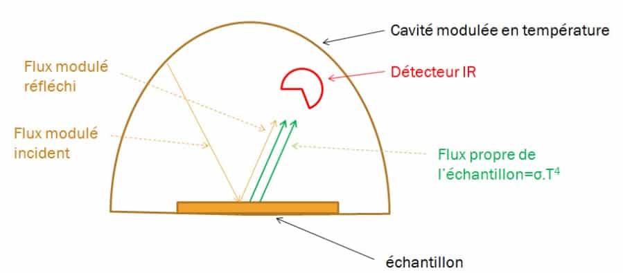
Figure 11
Principle of the reflectometric measurement method with a modulated source
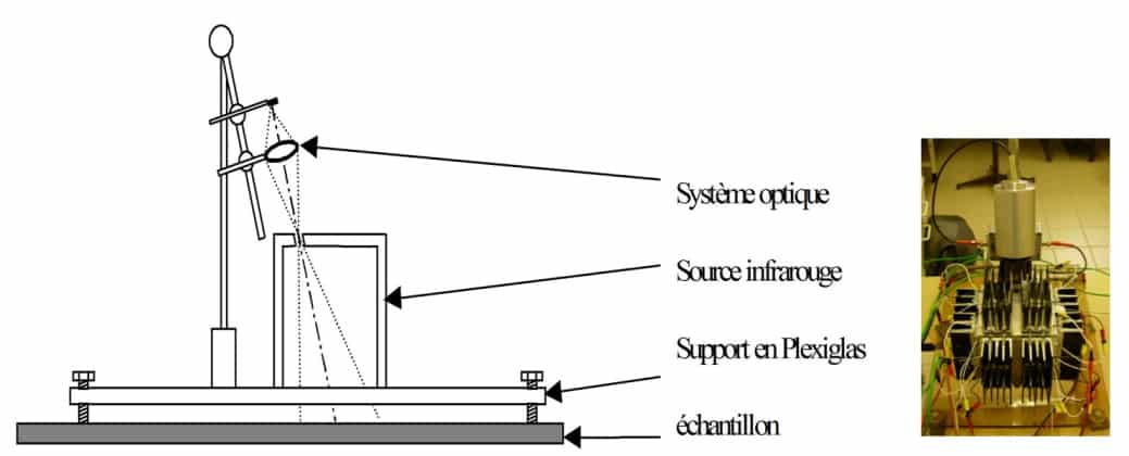
Figure 12
Diagram and photo of the measurement device developed at CERTES
Another method for modulating the hemispherical flow is to use a three-dimensional chopper. This device has been patented by ParisXII University. This device is presented below
EM3 from THEMACS Engineering:
The principle of this device is that described above. It consists in modulating a hemispherical radiation source by movable flaps. This avoids modulating the temperature cavity which is very slow. The diagram in Figure 21 shows the principle of modulation.
The source is cylinder B heated to a temperature slightly above ambient temperature. The movable cylinder C and the fixed screen D obscure the hemispherical source at a frequency of 10 Hz for the cylindrical wall (presence of 6 windows) and 5 Hz for the top part (presence of 3 windows). In this way, it is possible to differentiate a specular material from a diffusing material. One thermopile measures the incident flux and another the reflected flux. The ratio of the reflected flux does not depend on the level emitted by the source.
This emissometer must be previously calibrated using two known emissivity surfaces. We generally take a very highly emissive surface (Nextel paint, 3M ™) and a very low emissive surface (diffusing aluminum). Figure 21 shows the general diagram (1), a detail of the movable and fixed shutters, and of the source covered with Nextel paint (3M ™) (2), an exploded view of the device (3) and a photo of the device The device is portable and must be connected to a computer allowing demodulation of the signals by FFT.
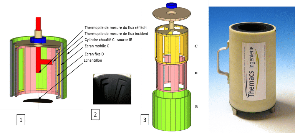
Figure 13
EM3 emissometer from THEMACS Engineering
4 To go further
Several general documents can complete this study on emissivity measurements. These include:
– “Measurement of Thermal Radiation Properties of Solids”, [13]. This document is the set of interventions from a 1962 congress on the radiative properties of materials. Despite the age of this publication, it comprehensively lists a large number of emissivity measurement devices used in the aeronautical field. If the technologies have strongly evolved since then, the measurement principles of these devices remain current.
– “Measurement Techniques for Thermal Radiation Properties”, [12]. In the same way, this document reviews the state of the art in 1990. New devices are described.
– “Spacecraft Thermal Control Coatings References”, [11]. This NASA reference document, which is one of the most recent, first describes the quantities measured. Then, a theoretical calculation linking the complex indices of the materials and the radiative properties is exposed. The various measurement methods are then described. At the end of the document, measurements on materials frequently used in the aerospace field are presented. This document, like the first cited above, also describes the optical properties in the visible; these are also important to know in order to deduce the thermal balance of a satellite subjected to solar radiation
5 Bibliography
- Maldague, X.P. Theory and practice of infrared technology for non destructive testing, . s.l. : Ed. Wiley, 2001.
- Kauder, L. Spacecraft Thermal Control Coatings References, NASA-TP-2005-212792. 2005.
- P. Lorrain, D.R. Corson. Champs et ondes électromagnétiques. s.l. : Armand Collin.
- Rubin, M., Arasteh, D. et Hartmann, J. A correlation between normal and hemispherical emissivity of low emissivity coatings on glass. s.l. : Int. Comm. Heat Mass Transfer, 1987.
- Blain, B. J. et Douglas, R. W. Infra-red optical constants of glasses. 1965.
- D. Janssen, J. Lohrengel. investigation and development of a method for the measurement of the emissivity of glass. s.l. : BCR european community, 1991. EUR 13487 EN.
- GEOTTI-BIANCHINI, F. Total hemispherical emissivity of coated glass. s.l. : European community, 1993. EUR 14758 EN.
- C. Fabron, A. Meurat. Measurement of total hemispheric emissivity at low temperature. s.l. : International Symposium on nvironnemental Testing for Space Program, Liège, Belgium, 2001.
- J. Hameury, B. Hay, J. R. Filtz. Measurement of Total Hemispherical Emissivity Using. s.l. : Int. J. Thermophys, 1607, 2007.
- S. Moghaddam, J. Lawler, J. Currano. Novel method for measurement of total hemispherical emissivity. s.l. : J. Thermophys. Heat Transfer, 2007.
- A. Mazikowski, K .Chrzanowski. Non-contact multiband method for emissivity measurement. s.l. : Infrared Phys. Technol., 91, 2003.
- L. Hanssen, S. Mekhontsev, V. Khromchenko. Infrared Spectral Emissivity Characterization Facility at NIST, . s.l. : Thermosense XXVI, edited by Douglas D. Burleigh, K. Elliott Cramer,G. Raymond Peacock,Proc. of SPIE Vol. 5405, SPIE, Bellingham,WA, 2004.
- L. Del Campo, R.B. Perez-Saez, X. Esquisabel, I. Fernandez, M.J. Tello. New experimental device for infrared spectral directional emissivity measurements in a controlled environment. s.l. : Review Of Scientific Instruments, vol. 77, 113111, 1-8, 2006.
- V. Vitkovskii, V. G. Gorshenev, Y. F. Potapov. Measurement of Spectral Directional Emissivity of Materials and Coatings in the Infrared Region of Spectrum. s.l. : Thermal Engineer , 245-248 Vol. 56-3, 2009.
- A. Pantinakis, N. Kortsalioudakis. A Simple High-Sensitivity Radiometer in the Infrared for Measurements of the Directional Total Emissivity of Opaque Materials at Near-Ambient Temperatures. s.l. : International Journal of Thermophysics, 1843-1854 Vol. 22-6, 2001.
- L.M. Hanssen, S. Kaplan. Infrared diffuse reflectance instrumentation and standards at NIST. s.l. : Anal. Chim. Acta, 289 , 1999.
- D. Especel, S. Matteï. Total Emissivity Measurement Without Use of an Absolute Reference. s.l. : Infrared Phys. Technol., 777-784 vol.37, 1996.
- L. Ibos, M. Marchetti, A. Boudenne, S. Datcu, J.Livet, Y. Candau. Infrared emissivity measurement device : Principle and applications. s.l. : Meas. Sc. Tech., 2950, 2006.
- M.Siroux. Développement de techniques de mesure de l’émissivité de matériaux opaques à température ambiante. Approches radiométrique et calorimétrique en régime périodique. s.l. : Thèse Université Paris 12, 1996.
Notre équipe vous conseille pour répondre au mieux à vos attentes
